In industrial process engineering, falling film evaporators (FFEs) are advanced thin-film evaporation systems renowned for high heat transfer efficiency, gentle processing of thermal-sensitive materials, and energy optimization. Widely deployed across chemical processing, pharmaceutical manufacturing, food & beverage, and wastewater treatment sectors, FFEs excel in concentrating solutions, recovering solvents, and processing viscous or heat-labile feeds. This article systematically elaborates on the technical working principle of FFEs, compares them with complementary evaporator technologies (rising film, wiped film), details industrial applications, and highlights key operational advantages and considerations—aligned with international engineering standards (e.g., ASME BPVC, DIN 28053).
1. Core Definition & Classification
A
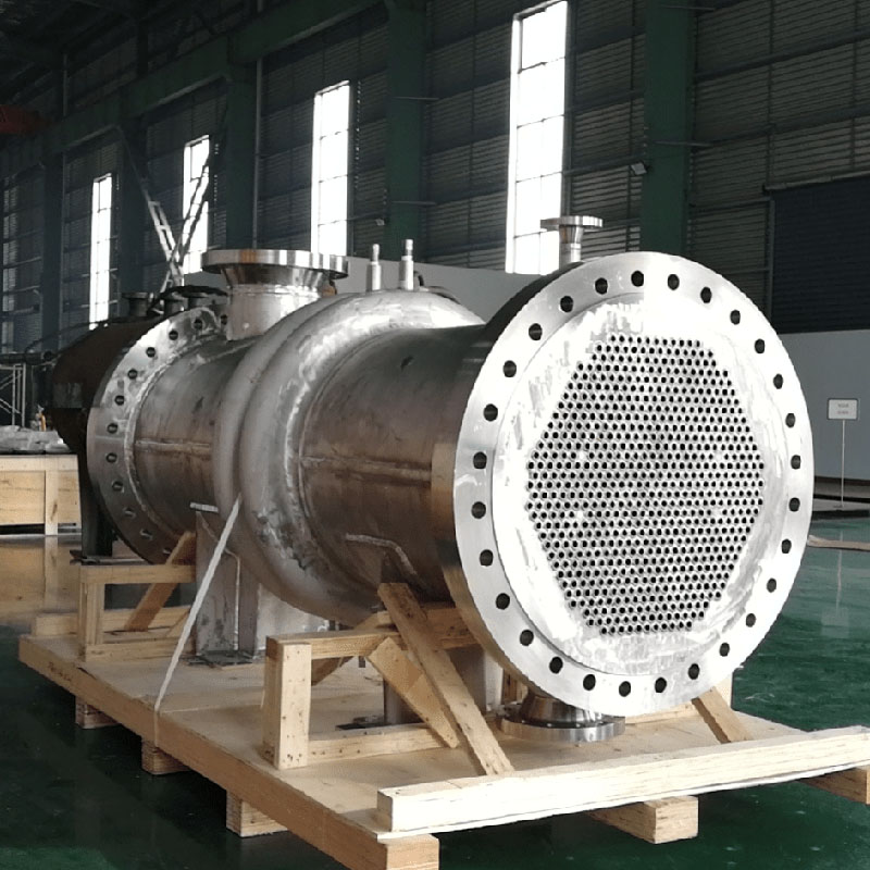
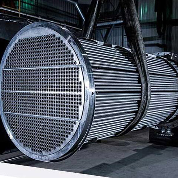
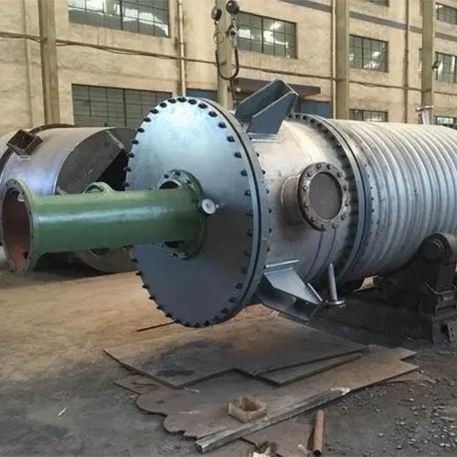
falling film evaporator is a continuous, shell-and-tube heat exchanger where the feed liquid forms a thin, gravity-driven film on the inner surface of vertical tubes. It belongs to the "thin-film evaporator" category (film thickness typically 0.1–1 mm), distinguishing it from conventional batch evaporators (e.g., jacketed kettles) by minimizing thermal resistance and maximizing mass transfer rates. Key design features include a precision liquid distributor, vertical tube bundle, shell-side heating jacket, and vapor-liquid separator—all optimized for laminar or turbulent film flow (Reynolds number Re = 500–2000 for optimal heat transfer).
2. Working Principle: Technical Mechanism
The operation of a falling film evaporator follows a sequential, thermodynamically optimized workflow, governed by principles of convective heat transfer and phase change:
Step 1: Feed Distribution & Film Formation
- The feed liquid (e.g., aqueous solutions, organic solvents, viscous slurries) is preheated to near its boiling point (typically 5–10°C below saturation) and introduced at the top of the evaporator via a precision liquid distributor. Common distributor designs include slot distributors, weir distributors, or spray nozzles—engineered to ensure uniform liquid distribution across the tube bundle.
- Gravity drives the liquid downward along the inner surface of the vertical tubes, forming a continuous, thin film (0.1–1 mm thick). Uniform film formation is critical: uneven distribution (e.g., channeling, dry spots) reduces heat transfer efficiency and risks fouling or thermal degradation.
Step 2: Heat Transfer & Evaporation
- The shell side of the tube bundle is heated by a thermal medium (e.g., saturated steam, hot oil, or process waste heat) at a temperature 10–30°C above the feed’s boiling point. Heat is transferred to the liquid film via convective heat transfer (dominant mechanism) and conductive heat transfer (negligible in thin films).
- The thin film minimizes thermal resistance (typically 1–5 × 10⁻³ m²·K/W), resulting in high heat transfer coefficients (h = 500–1000 W/m²·K)—2–3x higher than batch evaporators. This enables rapid evaporation: volatile components (solvents, water) vaporize at the film surface, forming a vapor stream that flows co-currently (with the liquid film) or counter-currently down the tubes.
Step 3: Vapor-Liquid Separation
- At the bottom of the tube bundle, the two-phase mixture (concentrated liquid + vapor) enters a vapor-liquid separator (also called a disengagement chamber). The separator uses gravitational settling, cyclonic action, or demister pads to separate the vapor from the concentrated liquid (raffinate).
- The vapor is routed to a condenser (for solvent recovery or condensation) or further processed (e.g., vacuum systems for low-boiling-point feeds). The concentrated liquid is collected at the separator bottom and discharged for downstream use or additional processing.
Step 4: Operational Control Parameters
- Operating Pressure: Often run under vacuum (5–50 kPa absolute) to lower the feed’s boiling point, minimizing thermal stress on heat-sensitive materials (e.g., pharmaceuticals, food ingredients).
- Film Flow Regime: Optimized for turbulent or transitional flow (Re = 500–2000) to enhance heat transfer; laminar flow (Re < 500) is avoided due to lower h values.
- Temperature Delta (ΔT): Maintained at 10–30°C between the heating medium and feed to balance evaporation rate and product quality.
3. Comparative Analysis with Other Evaporator Types
FFEs are often compared to rising film evaporators (RFEs) and wiped film evaporators (WFEs), with distinct tradeoffs in design, efficiency, and application suitability:
| Parameter | Falling Film Evaporator (FFE) | Rising Film Evaporator (RFE) | Wiped Film Evaporator (WFE) |
|------------------------------|---------------------------------------------------------------------------------------|---------------------------------------------------------------------------------------|---------------------------------------------------------------------------------------|
| Film Driving Force | Gravity | Vapor-induced lift (from boiling liquid at tube base) | Mechanical wiper blades (rotating at 500–3000 RPM) |
| Viscosity Range | 1–1000 mPa·s (handles moderate viscosity) | 0.1–100 mPa·s (optimal for low viscosity; poor for high viscosity) | 100–100,000+ mPa·s (handles extreme viscosity and fouling-prone feeds) |
| Heat Transfer Coefficient | 500–1000 W/m²·K (high efficiency) | 300–800 W/m²·K (lower than FFE for similar feeds) | 800–1500 W/m²·K (highest efficiency, due to forced film renewal) |
| Thermal Sensitivity | Excellent (low ΔT, short residence time: 1–10 seconds) | Good (residence time: 5–20 seconds) | Superior (ultra-short residence time: <1 second) |
| Fouling Resistance | Moderate (prone to fouling with crystalline or sticky feeds) | Low (fouling risks higher due to boiling-induced deposition) | High (wiper blades prevent fouling via mechanical scrubbing) |
| Capital & Operational Cost | Moderate (simpler design than WFE; lower energy than RFE) | Low (basic design; higher energy than FFE) | High (complex mechanical design; higher maintenance and energy costs) |
| Key Applications | Solvent recovery, food concentration, chemical solution concentration | Brine concentration, low-viscosity aqueous solutions | Polymer processing, high-viscosity slurries, fouling-prone pharmaceuticals |
4. Industrial Applications
FFEs are valued for their versatility and gentle processing, making them indispensable in key sectors:
4.1 Pharmaceutical & Fine Chemicals
- Solvent Recovery: Concentration and recovery of organic solvents (e.g., methanol, ethanol, acetone) from reaction mixtures, compliant with GMP (Good Manufacturing Practices) and EPA regulations.
- Active Pharmaceutical Ingredient (API) Processing: Concentration of heat-sensitive APIs (e.g., peptides, biologics) and intermediates, minimizing thermal degradation (operating temperatures 40–80°C under vacuum).
- API Purification: Removal of water or solvents from crystallization feeds, ensuring product purity (99.5%+).
4.2 Food & Beverage
- Liquid Concentration: Concentration of fruit juices (orange, apple), dairy products (milk, whey protein), and natural extracts (herbal tinctures), preserving bioactive compounds (vitamins, antioxidants) and sensory properties (flavor, color).
- Syrup Production: Concentration of sugar solutions (glucose, fructose) for confectionery and beverage applications, operating at 60–80°C to avoid caramelization.
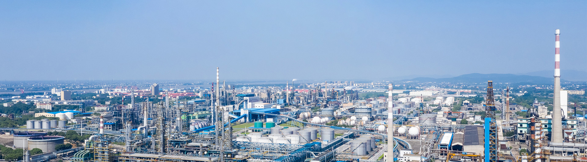
4.3 Chemical & Petrochemical
- Solution Concentration: Concentration of inorganic salts (e.g., sodium chloride, ammonium sulfate), organic acids (citric acid, lactic acid), and polymer solutions (polyvinyl alcohol, polyethylene glycol).
- Corrosive Feed Processing: Utilization of corrosion-resistant tube materials (Hastelloy, titanium, glass-lined steel) to handle acidic or alkaline feeds (e.g., sulfuric acid solutions, caustic soda).
4.4 Wastewater Treatment
- Brine Concentration: Recovery of water from industrial brines (e.g., desalination reject streams) and concentration of dissolved solids for safe disposal.
- VOC Recovery: Extraction and recovery of volatile organic compounds (VOCs) from industrial wastewater, reducing environmental impact and complying with EPA Clean Water Act standards.
5. Technical Advantages
FFEs offer distinct engineering and operational benefits over conventional evaporators:
- High Heat Transfer Efficiency: Thin film design minimizes thermal resistance, delivering heat transfer coefficients 2–3x higher than batch evaporators, reducing equipment footprint and processing time.
- Energy Optimization: Operates at lower temperatures (via vacuum) and requires 20–30% less energy than rising film or batch evaporators; compatible with waste heat integration (e.g., steam from other processes).
- Gentle Processing: Short residence time (1–10 seconds) and low ΔT minimize thermal degradation of heat-sensitive materials, preserving product quality and functionality.
- Viscosity Flexibility: Handles feeds with viscosity ranging from 1–1000 mPa·s, suitable for both dilute solutions and moderate-viscosity slurries.
- Scalability: Modular tube bundle design allows capacity scaling from lab-scale (10–100 kg/h) to industrial-scale (10,000+ kg/h) with consistent performance.
6. Operational Considerations
To maximize efficiency and reliability, key operational challenges must be addressed:
- Fouling Mitigation: Crystalline, organic, or particulate fouling can reduce heat transfer efficiency. Mitigation strategies include:
- Pre-treatment of feeds (filtration, pH adjustment) to remove solids or fouling precursors.
- Regular cleaning via CIP (Clean-in-Place) systems (chemical cleaning with acids, alkalis, or enzymes) or mechanical cleaning (for tube bundles).
- Film Uniformity: Poor liquid distribution (channeling, dry spots) leads to uneven evaporation and potential tube damage. Solutions include:
- Precision-engineered distributors (e.g., slot-type with flow meters) to ensure uniform liquid coverage.
- Minimum feed flow rate control (to maintain film integrity; typically 0.5–1 m/s liquid velocity).
- Capacity Limitations: Maximum capacity is constrained by tube length (typically 3–6 meters), diameter (25–50 mm), and number of tubes. For high-capacity applications, parallel evaporator trains are used.
- Initial Capital Investment: Higher upfront cost than rising film or batch evaporators due to precision components (distributors, corrosion-resistant materials), offset by long-term energy and maintenance savings.
7. Conclusion
Falling film evaporators represent a cornerstone of modern industrial evaporation, leveraging gravity-driven thin film flow to achieve high heat transfer efficiency, gentle processing, and energy optimization. Their working principle—rooted in uniform film formation, efficient convective heat transfer, and effective vapor-liquid separation—makes them ideal for thermal-sensitive, moderate-viscosity feeds across pharmaceuticals, food, chemicals, and wastewater treatment.
When compared to rising film and wiped film evaporators, FFEs strike a balance between efficiency, cost, and versatility, making them the preferred choice for most industrial concentration and solvent recovery applications. By addressing operational challenges (fouling, film uniformity) and leveraging modular design, FFEs deliver consistent performance, preserve product quality, and support sustainable processing practices.
For process engineers and plant operators, understanding the technical nuances of falling film evaporators enables informed equipment selection, process optimization, and long-term operational excellence—reinforcing their role as a critical component in efficient, high-quality industrial manufacturing.