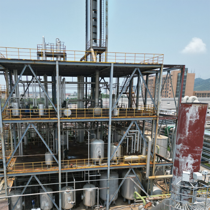
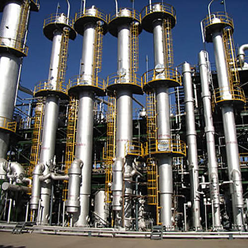
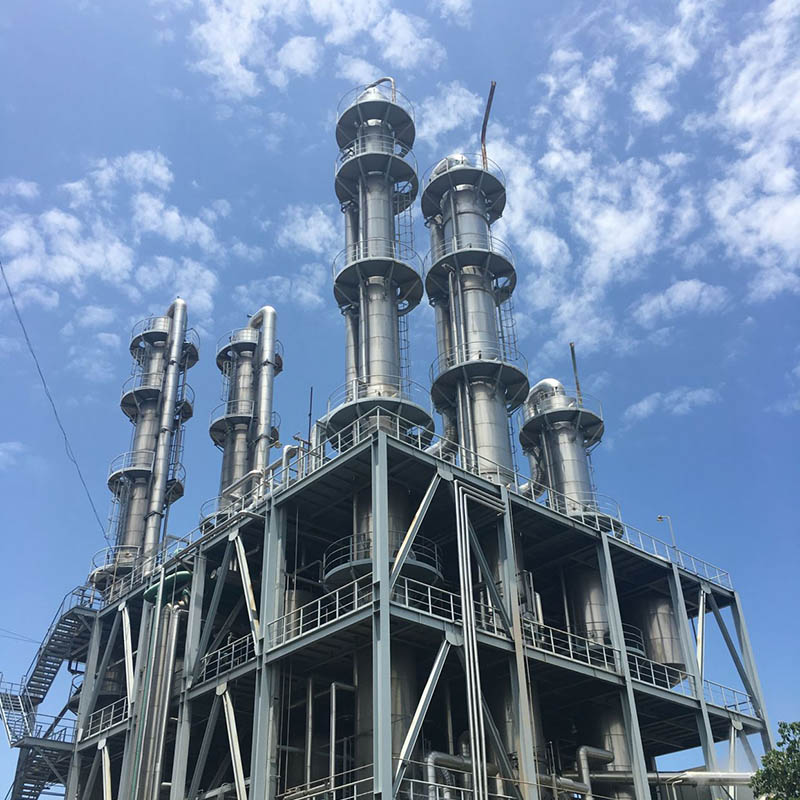
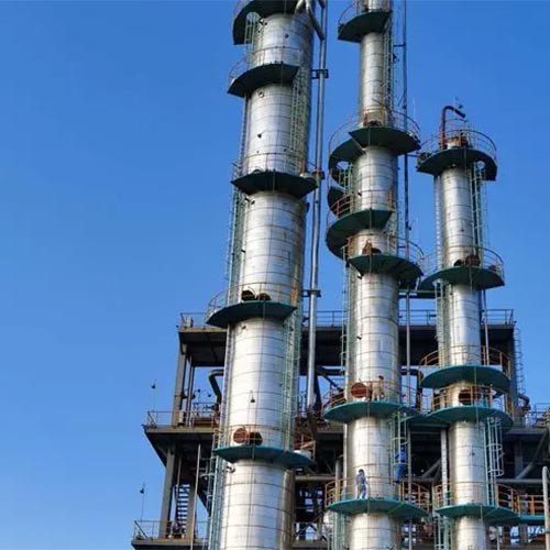
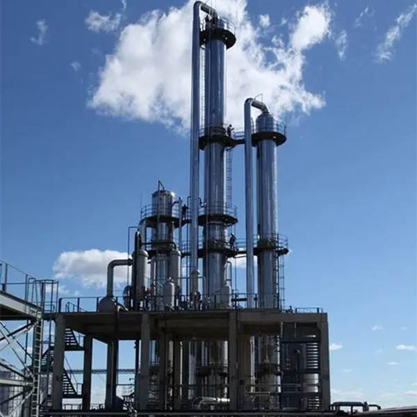
A distillation tower (also called a distillation column or fractionating column) is a vertical, industrial-scale separation device designed to fractionate liquid or vapor mixtures into their individual components based on differences in volatility (a property inversely related to boiling point: more volatile components have lower boiling points and vaporize more easily). Critical in petrochemical, oil refining, and chemical manufacturing, these towers enable the production of fuels (gasoline, diesel), solvents (ethanol, methanol), and high-purity chemicals by leveraging the principle of vapor-liquid equilibrium (VLE)—the dynamic balance where vapor and liquid phases coexist, with more volatile components concentrated in the vapor and less volatile components in the liquid. This article breaks down the tower’s design, operational principles, key components, and industrial applications—aligned with chemical engineering standards (e.g., ASTM D2892 for crude oil distillation, ISO 6570 for packed column performance).
1. Foundational Principle: Vapor-Liquid Equilibrium (VLE)
Distillation towers rely on VLE to drive separation. When a liquid mixture is heated, its more volatile components (lower boiling points) vaporize first. As this vapor rises and contacts a cooler liquid stream (reflux, explained later), it condenses—transferring heat and mass to the liquid. This interaction enriches the vapor with volatile components and the liquid with less volatile components. Repeating this cycle across multiple “stages” (trays or packing) in the tower achieves progressive separation, producing highly purified fractions.
For example, in crude oil distillation:
- Light hydrocarbons (e.g., propane, boiling point -42°C) are most volatile—they rise to the tower’s top.
- Heavy hydrocarbons (e.g., asphalt, boiling point >500°C) are least volatile—they remain at the tower’s bottom.
- Intermediate fractions (gasoline, diesel) collect at mid-tower levels, corresponding to their boiling points.
A distillation tower’s design is modular, with components working in tandem to optimize vapor-liquid contact and separation efficiency:
| Component | Location | Function | Design Variations |
|--------------------------|-----------------------------------|--------------------------------------------------------------------------|-----------------------------------------------------------------------------------|
| Column Shell | Entire structure | Vertical, cylindrical vessel (5–100 m tall, 1–10 m diameter) that houses internal components; constructed from corrosion-resistant steel (e.g., 316 stainless steel for chemical service). | - Atmospheric columns (operate at ambient pressure, for crude oil). <br> - Vacuum columns (operate at sub-atmospheric pressure, to separate high-boiling components without thermal degradation). |
| Internals: Trays or Packing | Inside the column (stacked vertically) | Provide a large surface area for vapor-liquid contact—critical for mass/heat transfer. | - Trays: Horizontal plates with perforations (sieve trays), valves (valve trays), or bubble caps (bubble-cap trays). Vapor rises through holes, bubbles through liquid on the tray, and exits to the next tray; liquid overflows via downcomers to the tray below. <br> - Packing: Loose or structured materials (e.g., Raschig rings, Pall rings, metal sheets) that create a tortuous path for vapor/liquid. Liquid flows downward over packing surfaces; vapor rises upward, interacting with the liquid film. |
| Reboiler | Bottom of the column | Heats the liquid “bottoms” (least volatile fraction) to generate vapor, which rises up the column to initiate separation. | - Kettle reboiler: Heats liquid in a separate vessel, with vapor returning to the column. <br> - Thermosiphon reboiler: Uses natural convection (heated liquid rises, cooled liquid falls) for continuous circulation—common in oil refineries. |
| Condenser | Top of the column | Cools the overhead vapor (most volatile fraction) into a liquid “distillate.” | - Total condenser: Condenses all vapor into liquid (used for producing liquid products like ethanol). <br> - Partial condenser: Condenses only a portion of vapor; uncondensed vapor (e.g., natural gas) is collected separately. |
| Reflux System | Between condenser and column top | Returns a portion of the condensed distillate (called “reflux”) back to the column’s top tray/packing. Reflux provides the cool liquid needed for vapor-liquid contact, improving separation efficiency. | - Reflux drum: Stores condensed distillate; a pump controls reflux flow rate (typically 1–10x the product withdrawal rate). <br> - Reflux ratio: Ratio of reflux flow to product flow (higher ratios = better separation but higher energy use). |
| Feed Inlet | Mid-column (varies by mixture) | Introduces the raw mixture (“feed”) into the column at a height matching the feed’s volatility profile (called the “feed tray”). This minimizes energy waste by aligning the feed with the column’s internal concentration gradient. | - Subcooled liquid feed: Feed is cooler than the column’s temperature at the feed tray—adds liquid to the column. <br> - Superheated vapor feed: Feed is hotter than the column’s temperature—adds vapor to the column. |
| Product Outlets | Top, middle, and bottom | Extract purified fractions at different heights: <br> - Top outlet: Most volatile fraction (e.g., gasoline in crude distillation). <br> - Side draws (middle): Intermediate fractions (e.g., diesel, kerosene). <br> - Bottom outlet: Least volatile fraction (e.g., heavy fuel oil, asphalt). | - Valves or pumps regulate flow rates; on-line analyzers (e.g., gas chromatographs) monitor purity in real time. |
3. Step-by-Step Operation of a Distillation Tower
The tower’s operation follows a continuous, closed-loop process optimized for steady-state separation. Below is a detailed breakdown using crude oil distillation as an example:
Step 1: Feed Preparation & Introduction
- The raw mixture (e.g., crude oil) is preheated (to 250–350°C) and pumped into the column via the feed inlet—typically at the mid-column “feed tray.” This preheating reduces the reboiler’s energy load and ensures the feed matches the column’s temperature at that height.
Step 2: Vapor Generation (Reboiler)
- At the column’s bottom, the reboiler heats the liquid bottoms (heavy crude components) to 350–400°C. This generates vapor rich in intermediate and light hydrocarbons, which rises upward through the column’s trays or packing.
Step 3: Vapor-Liquid Contact (Separation Stages)
- As vapor rises, it interacts with liquid flowing downward (from the reflux system or higher trays):
- On Trays: Vapor bubbles through the liquid layer on each tray, transferring heat (vapor condenses, liquid vaporizes) and mass (volatile components move to vapor, less volatile components move to liquid). Liquid overflows via downcomers to the next lower tray, becoming progressively richer in heavy components.
- In Packing: Liquid flows downward as a thin film over packing surfaces; vapor rises through the packing’s gaps, contacting the film. This continuous interaction achieves the same separation as trays but with lower pressure drop (ideal for vacuum columns).
Step 4: Overhead Vapor Condensation
- Vapor reaching the column’s top (rich in light hydrocarbons like gasoline) flows to the condenser, where it is cooled to 40–60°C (using cooling water or air). This condenses the vapor into liquid distillate, which collects in a reflux drum.
Step 5: Reflux & Product Withdrawal
- A portion of the distillate is pumped back to the column’s top as reflux (reflux ratio = 3–5 for crude oil). This reflux provides the cool liquid needed to “scrub” rising vapor, removing heavy contaminants and improving light fraction purity.
- The remaining distillate is withdrawn as the top product (e.g., gasoline). Intermediate products (e.g., diesel, kerosene) are extracted via side draws at mid-column heights, where their concentration is highest.
- The least volatile components (heavy fuel oil, asphalt) remain as liquid bottoms, which are withdrawn from the column’s base and sent to downstream processes (e.g., cracking units for further refinement).
Step 6: Process Control
- Sensors and controllers maintain steady-state operation:
- Temperature sensors: Monitor tray temperatures to adjust reboiler heat (higher temperature = more vapor generation).
- Pressure sensors: Regulate column pressure (critical for vacuum columns, where pressure affects boiling points).
- Flow meters: Adjust reflux rate and product withdrawal to maintain desired purity (e.g., 95% ethanol in solvent production).
4. Types of Distillation Towers
Towers are classified by their internal design (tray vs. packing) and operating pressure, each suited to specific applications:
| Tower Type | Key Design Feature | Ideal Applications |
|---------------------------|-----------------------------------------------------------------------------------|-----------------------------------------------------------------------------------|
| Tray Column | Uses perforated, valve, or bubble-cap trays; easy to maintain and scale. | High-volume, robust separations (e.g., crude oil distillation, petrochemical production) where fouling (solid buildup) is a risk. |
| Packed Column | Uses structured/loose packing; lower pressure drop, higher efficiency for small-diameter columns. | Low-pressure or vacuum separations (e.g., separating high-boiling hydrocarbons to avoid thermal degradation), and fine chemical separations (e.g., pharmaceutical solvent purification). |
| Atmospheric Column | Operates at ambient pressure (1 atm); no vacuum system needed. | Separating low-to-medium boiling mixtures (e.g., crude oil into gasoline, diesel). |
| Vacuum Column | Operates at sub-atmospheric pressure (0.01–0.1 atm); reduces boiling points of heavy components. | Separating high-boiling fractions (e.g., crude oil bottoms into lubricating oil, asphalt) without thermal cracking. |
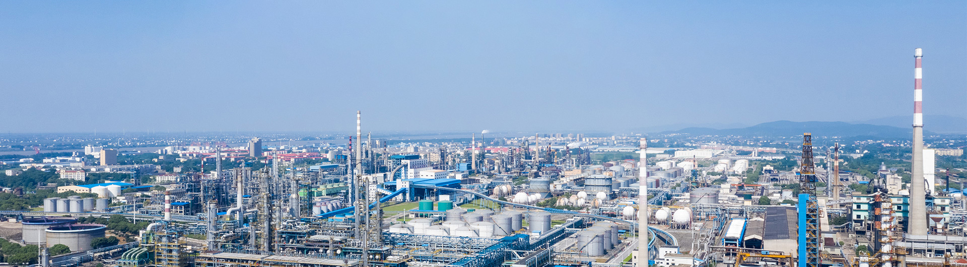
5. Industrial Applications
Distillation towers are ubiquitous in process industries, enabling the production of essential materials:
5.1 Oil Refining
- Primary Use: Fractionate crude oil into marketable fuels and feedstocks.
- Products:
- Top: Liquefied Petroleum Gas (LPG, propane/butane).
- Mid: Gasoline (C5–C12), kerosene (C12–C15), diesel (C15–C20).
- Bottom: Heavy fuel oil, asphalt, and feedstocks for catalytic cracking (to make more gasoline).
5.2 Chemical Manufacturing
- Primary Use: Purify solvents, monomers, and intermediates.
- Examples:
- Ethanol purification (removing water to 99.5% “absolute ethanol” for pharmaceuticals).
- Separation of ethylene/propylene (monomers for plastics) from naphtha crackers.
5.3 Petrochemicals
- Primary Use: Produce high-purity hydrocarbons for polymers and specialty chemicals.
- Example: Separating benzene, toluene, and xylene (BTX) from reformate (a crude oil derivative) for plastic and dye production.
5.4 Cryogenic Distillation
- Primary Use: Separate air into oxygen, nitrogen, and argon (requires ultra-low temperatures: -183°C for oxygen, -196°C for nitrogen).
- Applications: Steel manufacturing (oxygen for combustion), food packaging (nitrogen for inert atmosphere), and electronics (argon for welding).
6. Challenges & Optimization
While distillation towers are highly effective, they face key challenges that drive ongoing optimization:
6.1 Energy Intensity
- Distillation accounts for ~40% of energy use in chemical plants (due to reboiler heating and condenser cooling).
- Optimizations:
- Heat integration (using waste heat from other processes to preheat the feed).
- Variable reflux ratios (lower ratios for less strict purity requirements).
- Advanced controls (AI-based systems to adjust pressure/temperature in real time).
6.2 Fouling & Maintenance
- Trays or packing can foul with solids (e.g., coke in crude oil columns), reducing efficiency.
- Solutions:
- Periodic cleaning (chemical or mechanical).
- Use of fouling-resistant materials (e.g., Hastelloy for corrosive feeds).
6.3 Environmental Impact
- Volatile organic compound (VOC) emissions from column vents are a concern.
- Mitigations:
- Closed-loop condensers to capture emissions.
- Carbon capture systems (for large-scale towers).