Natural gas dehydration towers are critical components of upstream and midstream natural gas processing systems, designed to remove water vapor from raw natural gas to meet pipeline specifications, prevent equipment damage, and ensure safe, efficient transport and utilization. Raw natural gas extracted from reservoirs is saturated with water vapor (often 50–1,000 lb of water per million cubic feet (MMscf) of gas), which poses severe risks: the formation of hydrates (ice-like crystalline solids that clog pipelines and valves), accelerated corrosion of carbon steel infrastructure, and reduced energy density of the gas. Dehydration towers address these risks by leveraging either liquid absorption (e.g., glycol-based systems) or solid adsorption (e.g., molecular sieve systems) to reduce water content to industry standards (typically ≤7 lb/MMscf for pipeline transport, and ≤0.1 lb/MMscf for liquefied natural gas (LNG) production). This article details the design, working principles, system types, operational criticality, and industry standards of natural gas dehydration towers—aligned with API 510 (pressure vessel inspection) and GPA 2140 (water content measurement in natural gas).
1. Core Purpose & Operational Risks Addressed
The primary function of a natural gas dehydration tower is to achieve spec-compliant water content in natural gas, mitigating three existential risks to the natural gas value chain:
1.1 Hydrate Formation
Hydrates form when water vapor in natural gas combines with light hydrocarbons (methane, ethane, propane) under low temperatures (<10°C) and high pressures (>500 psi)—conditions common in pipelines and processing equipment. These solids:
- Clog valves, meters, and pipeline constrictions, causing pressure drops and operational shutdowns (costing $100,000+ per hour in lost production).
- Damage equipment (e.g., centrifugal compressors) due to abrasive wear.
Dehydration towers reduce water vapor below the “hydrate formation threshold,” eliminating this risk without relying on expensive chemical inhibitors (e.g., methanol) for long-term use.
1.2 Corrosion of Infrastructure
Water vapor reacts with acidic components in natural gas (e.g., hydrogen sulfide (H₂S), carbon dioxide (CO₂)) to form corrosive acids (e.g., sulfuric acid, carbonic acid). This accelerates:
- Internal corrosion of carbon steel pipelines (reducing service life from 20–30 years to 5–10 years if unaddressed).
- Leaks in storage tanks and processing vessels, posing safety hazards (e.g., gas releases) and environmental risks.
By removing water, dehydration towers minimize acid formation, extending the lifespan of capital-intensive infrastructure.
1.3 Compliance with Pipeline & End-Use Specifications
Regulatory bodies and pipeline operators mandate strict water content limits to ensure:
- Pipeline Transport: ≤7 lb/MMscf (per API 5L) to prevent hydrates and corrosion.
- LNG Production: ≤0.1 lb/MMscf (per ISO 16924) to avoid ice formation in cryogenic heat exchangers.
- Industrial/Residential Use: ≤5 lb/MMscf to maintain heating efficiency (water vapor reduces the calorific value of natural gas).
Dehydration towers are the only cost-effective technology to consistently meet these standards at scale.
2. Design & Key Components of Natural Gas Dehydration Towers
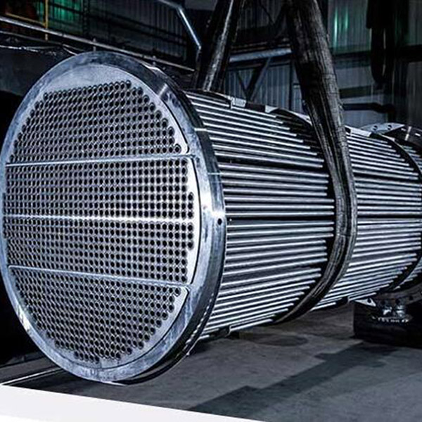
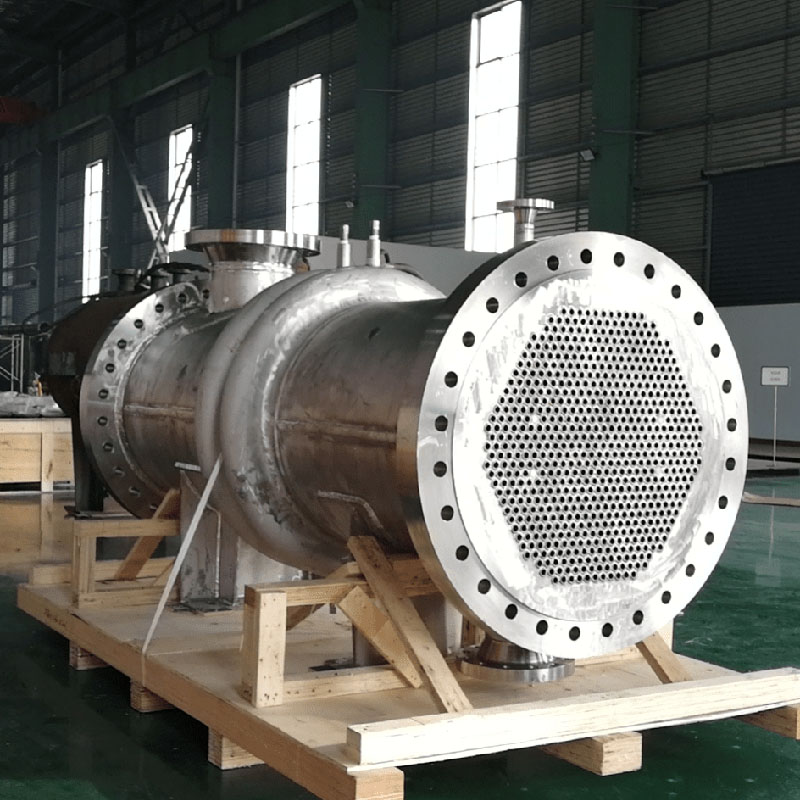
Natural gas dehydration towers are vertical, cylindrical pressure vessels (typically 3–10 ft in diameter, 10–40 ft in height) constructed from carbon steel (for sweet gas) or corrosion-resistant alloys (e.g., 316 stainless steel, duplex steel) for sour gas (high H₂S content). Their design varies by dehydration method (absorption vs. adsorption) but shares core components:
| Component | Function | Design Variations (Absorption vs. Adsorption) |
|--------------------------|--------------------------------------------------------------------------|-----------------------------------------------------------------------------------|
| Tower Shell | Pressure-containing vessel that houses the desiccant (liquid or solid) and facilitates gas-desiccant contact. | - Absorption Towers: Taller, with internal trays (sieve, valve) or packing (Raschig rings) to maximize gas-liquid contact. <br> - Adsorption Towers: Shorter, with a fixed bed of solid desiccant (e.g., molecular sieves) supported by a grid plate. |
| Desiccant System | The medium that captures water vapor from natural gas. | - Absorption: Liquid desiccants (e.g., triethylene glycol (TEG), diethylene glycol (DEG))—highly hygroscopic liquids that dissolve water. <br> - Adsorption: Solid desiccants (e.g., 3Å molecular sieves, silica gel, activated alumina)—porous materials that trap water molecules via surface adhesion. |
| Gas Inlet/Outlet Nozzles | Inlet (lower section) distributes gas uniformly across the desiccant; outlet (upper section) collects dried gas. | - Absorption: Inlet includes a distributor (e.g., spray nozzles) to disperse gas into the liquid desiccant. <br> - Adsorption: Inlet has a perforated baffle to prevent channeling (uneven gas flow through the solid bed). |
| Liquid Distributor (Absorption Only) | Sprays liquid desiccant uniformly over trays/packing to ensure full contact with rising gas. | - Uses spray nozzles or weir boxes to maintain a consistent liquid flow rate (critical for absorption efficiency). |
| Regeneration Unit Interface | Connects the tower to a system that reclaims saturated desiccant for reuse. | - Absorption: TEG-rich solution (saturated with water) flows to a reboiler (heated to 200–230°C) to evaporate water. <br> - Adsorption: Saturated molecular sieves are regenerated via hot dry gas (150–200°C) or vacuum to desorb water. |
| Pressure Relief System | Safety valves or rupture discs to protect the tower from overpressure (common during startup/shutdown). | - Complies with ASME BPVC Section VIII (pressure vessel design standards) to handle operating pressures of 500–2,500 psi. |
3. Two Primary Dehydration Systems: Absorption vs. Adsorption
Natural gas dehydration towers operate via two distinct technologies, each optimized for specific water content targets, gas volumes, and operational costs:
3.1 Glycol Absorption Towers (TEG Systems)
Glycol absorption is the most widely used dehydration method for large-scale upstream/midstream operations (e.g., gas processing plants, pipeline stations) due to its cost-effectiveness and scalability.
Working Principle
1. Gas-Liquid Contact: Raw natural gas enters the bottom of the tower and rises through trays or packing. A lean (low-water) TEG solution is sprayed from the top, flowing downward and contacting the gas.
2. Water Absorption: TEG dissolves water vapor from the gas (solubility of water in TEG is ~20% by weight at 25°C), with absorption efficiency >95%.
3. Desiccant Regeneration: Saturated (rich) TEG flows to a reboiler, where heat (200–230°C) evaporates water vapor (vented or condensed for disposal). Lean TEG is recycled back to the tower (reuse rate >99%).
4. Dried Gas Exit: Gas with ≤7 lb/MMscf water content exits the top of the tower, meeting pipeline specifications.
Key Advantages & Limitations
- Advantages: Low capital cost ($500,000–$2M for a 100 MMscf/day system), high throughput, and minimal maintenance.
- Limitations: Cannot achieve ultra-low water content (<1 lb/MMscf) required for LNG; TEG degradation (at >230°C) produces acidic byproducts that require neutralization.
Ideal Applications
- Pipeline transport of natural gas (meets ≤7 lb/MMscf standards).
- Upstream gas processing (e.g., at wellheads) for high-volume, medium-purity requirements.
3.2 Solid Adsorption Towers (Molecular Sieve Systems)
Solid adsorption towers are used for ultra-dry gas applications (e.g., LNG, compressed natural gas (CNG), and gas for chemical synthesis) where water content must be ≤0.1 lb/MMscf.
Working Principle
1. Dual-Tower Design: Most systems use two parallel towers (one in adsorption mode, one in regeneration mode) for continuous operation.
2. Adsorption Phase: Raw gas flows through a tower filled with 3Å molecular sieves (porous aluminosilicates with 3 angstrom pores—selective for water molecules, which are ~2.8 Å in diameter). Water is trapped in the sieve pores, with adsorption efficiency >99.9%.
3. Regeneration Phase: When the sieve bed is saturated, the tower switches to regeneration: hot dry gas (150–200°C) or vacuum is applied to desorb water, restoring the sieve’s adsorption capacity.
4. Ultra-Dry Gas Exit: Gas with ≤0.1 lb/MMscf water content exits for downstream processes (e.g., cryogenic LNG liquefaction).
Key Advantages & Limitations
- Advantages: Achieves ultra-low water content, no liquid handling (reduces corrosion risks), and compatibility with sour gas (molecular sieves are inert to H₂S).
- Limitations: Higher capital cost ($1–3M for a 100 MMscf/day system), lower throughput than TEG systems, and periodic sieve replacement (every 3–5 years).
Ideal Applications
- LNG production (prevents ice formation in cryogenic equipment).
- CNG for vehicles (avoids fuel system corrosion).
- Chemical feedstock gas (e.g., for methanol synthesis, where water deactivates catalysts).
4. Critical Operational Considerations
To ensure dehydration towers perform reliably, operators must monitor and optimize three key parameters:
4.1 Desiccant Quality & Regeneration Efficiency
- Absorption (TEG): Maintain TEG purity at >98% (via proper reboiler temperature control); TEG purity <95% reduces dehydration efficiency, leading to off-spec gas.
- Adsorption (Molecular Sieves): Monitor bed temperature during regeneration—insufficient heat (<150°C) leaves residual water, reducing adsorption capacity; excessive heat (>200°C) degrades sieves.
4.2 Gas Flow Distribution
- Poor gas distribution (e.g., channeling in adsorption towers, uneven liquid spray in absorption towers) reduces contact between gas and desiccant, leading to “bypassing” (untreated gas exiting the tower).
- Mitigation: Use flow distributors (baffles, spray nozzles) and periodic inspection of internal components (trays, packing) for fouling or damage.
4.3 Pressure & Temperature Control
- Pressure: Operate the tower at the lowest feasible pressure (consistent with upstream/downstream systems) to enhance water vapor removal (lower pressure increases the vapor pressure of water, improving desorption).
- Temperature: Cool raw gas to 20–30°C before entering the tower—higher temperatures reduce desiccant capacity (e.g., TEG absorbs 30% less water at 40°C vs. 20°C).
5. Industry Standards & Compliance
Natural gas dehydration towers must adhere to strict standards to ensure safety, performance, and regulatory compliance:
- Design: ASME BPVC Section VIII (pressure vessel design), API 5L (pipeline material compatibility).
- Performance: GPA 2140 (standard test method for water content measurement), ISO 13686 (water content limits for natural gas).
- Inspection: API 510 (pressure vessel inspection code), API 653 (tank inspection for liquid desiccant storage).